Know how a CNC router actually works, and you will spot production bottlenecks, precision limits, and capacity gaps before they cost you. Here’s every stage of the CNC router working process, broken down so you know exactly what the machine can handle and its value to your production.
What Is a CNC Router and Its Key Components
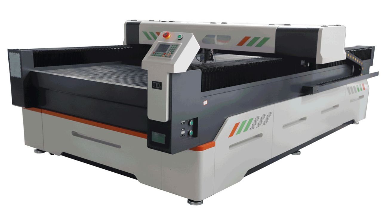
A CNC router is a machine that uses computer instructions to control a cutting tool to perform precise machining on sheet material. These instructions are known as G-code, which tells the CNC router the specific movement paths, feed rates, and cutting depths.
Most CNC routers are used for cutting non-metallic materials, such as medium-density fiberboard (MDF), plywood, acrylic sheets, and polyethylene sheets. You can also use them to cut softer metals like brass and aluminum. Cabinetry, advertising signs, and mold production all rely on CNC routers.
Frame and Gantry Structure
The frame and gantry structure is the main framework that supports the operation of the entire CNC router. Common materials include welded steel, cast iron, or die-cast aluminum.
During machining, it directly absorbs the cutting reaction forces and resists deformation through its own rigidity. At the same time, it dampens vibrations, so your machine can operate smoothly, and the machined parts are more dimensionally accurate.
Cutting Bed / Worktable
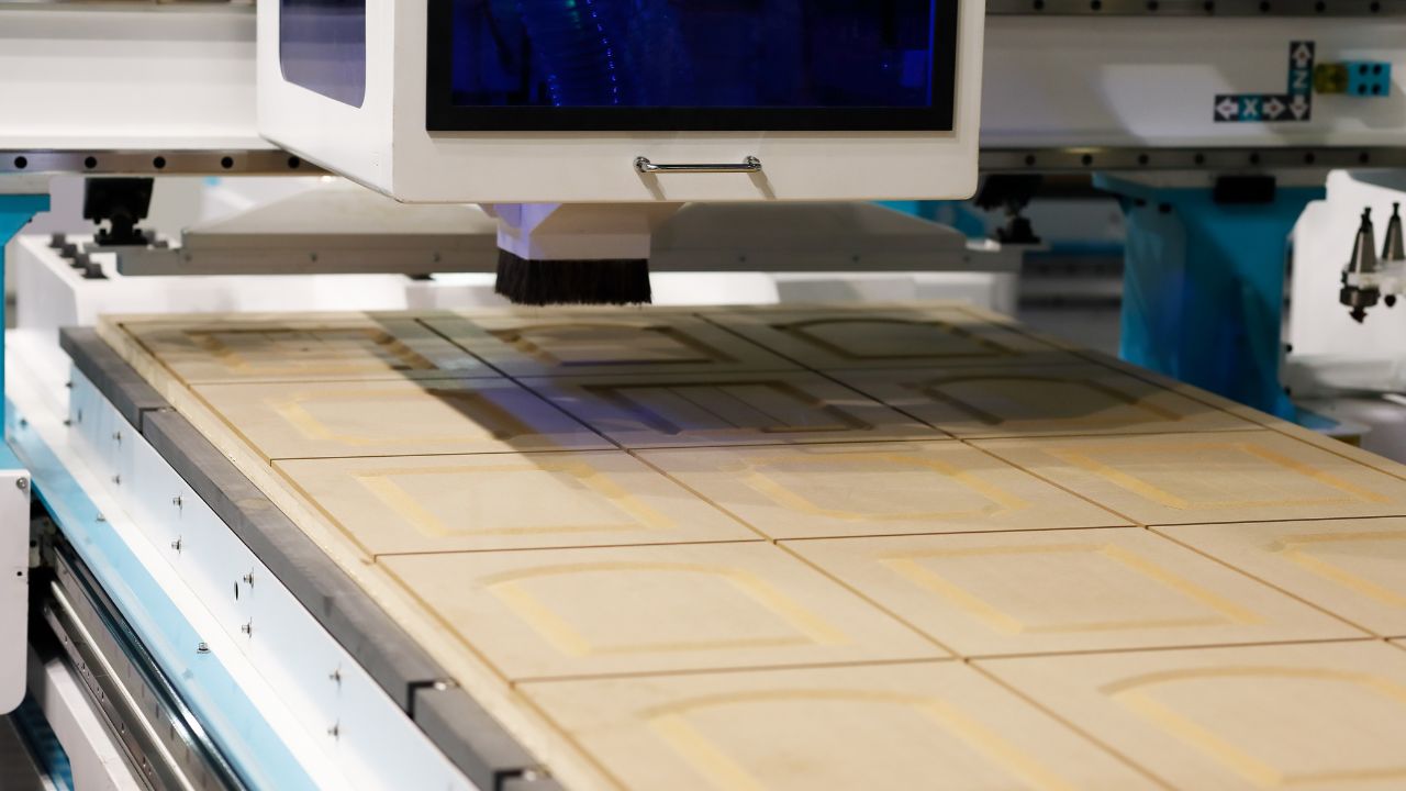
The worktable is located directly beneath the gantry and serves as a flat surface for placing and securing the material to be cut. Common types of worktables include vacuum hold-down beds and T-slot aluminum beds.
Vacuum hold-down beds create negative pressure using a vacuum pump located beneath the perforated plate, directly suctioning the sheet material into place. They offer quick clamping and an unobstructed surface, suitable for thin sheets and large-area sheets.
T-slot aluminum beds have T-shaped grooves. You can insert clamps or screws in the grooves to secure workpieces and prevent them from shifting under cutting forces. They are frequently used when machining thick plates, solid wood, or irregularly shaped parts.
Motors and Drive System
The motors and drive system are the power source for a CNC router. After the controller interprets the G-code, it sends pulse signals to the drive system. Motors will drive the gantry to move along the X, Y, and Z axes, performing precise 3D cutting and engraving.
The most common types of motors you’ll encounter are stepper motors or servo motors. Servo motors are more expensive than stepper motors, but they use closed-loop control, do not lose steps, and offer better precision and response.
A motor outputs rotational motion. If you want to convert that into linear motion, you’ll need a transmission mechanism. If your CNC router is large and you are looking for speed, you can choose a rack-and-pinion drive system. If you have strict precision requirements, use a ball screw or lead screw. Small CNC routers sometimes use timing belts as well. They’re lightweight but have limited rigidity.
Spindle
The spindle is mounted on the Z-axis of the gantry and serves as the core actuator of the CNC router.
It is driven by a built-in motor that clamps the cutting tool and rotates it at high speed to cut or engrave workpieces. A normal electric spindle can reach speeds of 12,000—24,000 revolutions per minute. You can adjust it flexibly based on the material and tool type.
If your CNC router is cutting soft materials such as foam or medium-density fiberboard, higher RPMs are more efficient. Lower RPMs can reduce tool wear and prevent burning, and they are suitable for hard materials like hardwood or aluminum.
CNC Controller and Software
The CNC controller is the command center of the entire CNC router. You use CAD/CAM software to generate G-code, and the controller interprets these instructions, converts them into electrical signals, and sends them in real time to the drive system, telling each axis where to move and how fast the spindle should rotate.
The control panel displays key data such as cutting speed, spindle speed, and error messages. During machining, you can adjust the feed rate or spindle speed at any time via the panel. If an error message appears, you can immediately stop the machine to troubleshoot the issue.
Dust Extraction
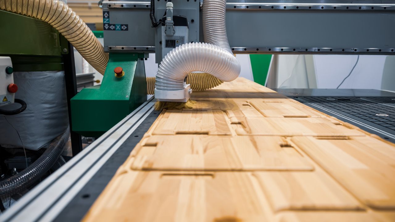
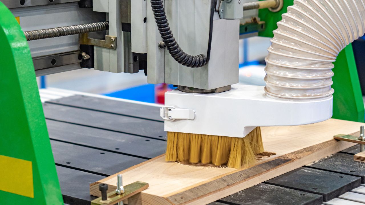
A CNC router generates a large amount of chips and dust during the cutting process. Through the dust collection port and ductwork, the dust extraction system removes debris from the work area in real time.
If you don’t clear away the chips promptly, the cutting tool will repeatedly grind against old chips—heat builds up, cut edges go rough, and tool life drops. Keeping airborne dust down also protects your staff’s health.
The Step-by-Step CNC Router Working Process
Design Creation in CAD
All CNC router processing requires a precise digital design before it can begin. You need to draw the shape and dimensions of the final workpiece in CAD software. This can be a 2D vector drawing or a 3D model.
2D files are generally used for cutting outlines and engraving flat patterns, but you’ll need 3D models for relief carving or curved surface machining.
The model formats must be compatible. The common 3D models are in STEP or STL format. For 2D vector files, you should use DXF, AI, or EPS formats. Any geometric error at this stage will be carried through all subsequent machining steps.
Toolpath Planning & G-Code Generation
You need to import your CAD files into the CAM software. It will convert your drawings into toolpaths that a CNC router can execute.
A toolpath is the route you map out for the tool—where to make the cut, follow what path, and how deep each cut should be. CAM software generates the corresponding G-code at the same time, turning that path into coordinate commands for each axis.
In CAM software, you need to set key parameters for the CNC router—such as cutting speed, depth of cut per pass, and tool type—based on the material and machining process. If the cutting speed is too fast, it may cause the material to burn. Cutting too deeply in a single pass can easily break the tool or leave vibration marks.
What you set here controls both how fast your machining runs and how clean the surface of the finished product looks when it’s done.
Machine Setup: Material, Tooling & Zero Point
With your design documents ready, it’s time to set up the machine. Every part of this stage feeds into machining accuracy—nothing here is optional.
Secure the material to the cutting bed—clamp or suction it firmly—to prevent any movement during cutting. Select the appropriate cutting tool and load it into the spindle.
| Tool types | Materials and processing effects |
| Spiral-rounded bit | Acrylic, smooth machining, good chip evacuation |
| Straight-toothed bit | Flat engraving, clean edges, smooth bottom surface |
| Long-reach router bits | Cutting soft materials |
If your CNC router is equipped with an automatic tool changer, multi-tool operations won’t require manual tool changes midway through.
After installing the cutting tool, you can set the zero points for the X, Y, and Z axes. You should pay special attention to the Z-axis zero point. If you set it too high, the tool won’t reach the material; if you set it too low, the tool will crash into the worktable. Finally, upload the G-code file to the CNC controller and prepare to run the program.
The Cutting Process: Axes in Motion & Spindle Action
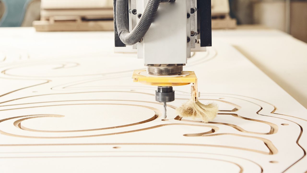
When you press the start button on the CNC router, the spindle will spin at high speed. The drive system will move it precisely along the X, Y, and Z axes, and the cutting tool will machine the material layer by layer along the predetermined path. Depending on your project, the machining process may involve profiling, pocketing, drilling, engraving, or 3D carving.
You need to closely monitor the machine’s operation—listen for any unusual cutting noises, observe the color of the chips and the condition of the cutting tools, and prevent any accuracy deviations or excessive tool wear.
Digital control means the same G-code gives you the same result every time—whether you’re running one prototype or a small batch.
Part Removal, Inspection & Edge Finish
After cutting is complete, remove the workpiece from the worktable. First, you need to clean any dust or debris left on the work surface to prepare for the next machining operation.
Check the dimensional accuracy and surface quality of the finished product. If there are burrs or minor tool marks on the edges, you can easily smooth them out with sandpaper or a deburring tool.
If your product has higher aesthetic or functional requirements, simple sanding may not be enough. You can sandblast or polish the final parts to inspection standards.
FAQ
What Are the Differences in How CNC Routers and Laser Cutters Work?
| Comparison criteria | CNC router | Laser cutter |
| Processing principles | The spindle rotates at high speed while clamping the cutting tool. Mechanical cutting | High-energy beam melting/vaporization |
| Cutting method | Physical contact, with cutting force | Non-contact |
| Applications | 3D carving, curved surface grooving | 2D flat cutting, surface marking |
| Trimmed edge effect | There may be burrs, so post-processing is required. | Acrylic edges feature a mirror-polished finish. |
| Applicable materials | Wood, plastic, soft metals | Thin metal, acrylic, and some materials produce smoke. |
| Machining thickness | Can cut thick plates, but is limited by Z-axis travel. | Better suited for thin sheets |
What Causes Chatter Marks on CNC Routed Parts, And How Do I Fix Them?
Chatter marks come from insufficient machine rigidity or mismatched cutting parameters. This is often seen when the workpiece is not securely clamped, the feed rate is too fast, the spindle speed is mismatched, the tool overhang is too long, or the chipload is too high.
Check the vacuum pump’s negative pressure. Increase the feed rate or reduce the spindle speed. You can switch to short-shank cutting tools with shorter cutting lengths and higher rigidity, and strictly limit the single cutting depth to no more than one time the tool diameter.
Do I Need Water Cooling or Air Cooling for My CNC Router Spindle?
| Advantages | Disadvantages | |
| Water cooling | Extremely precise temperature control, high cooling efficiency, and low operating noise. Suitable for 24-hour continuous, high-load cutting operations. | A water pump, water pipes, and regular maintenance of the water system are required to prevent scale buildup and blockages. You need to add antifreeze in the winter. |
| Air cooling | Comes with a built-in cooling fan. Simple structure. Ready to use out of the box. Low maintenance costs. Not susceptible to freezing. | Limited heat dissipation. Loud fan noise at high speeds. |
A water-cooling spindle is the right call if you run the CNC router more than 4 hours a day or frequently cut hard materials. An air-cooling spindle works fine for cold workshops or anyone who prefers a low-maintenance setup.
How to Prevent Acrylic Sheets from Melting During High-Speed CNC Routing?
Acrylic has a low melting point, about 160°C. If the spindle speed is too high, the feed rate is too slow, or heat is generated by tool friction, the acrylic will melt.
You should reduce the spindle speed to 12,000—18,000 RPM and push the feed rate up. Faster material throughput means less friction heat building up at any single contact point.
Equip the CNC router with an O-Flute bit. The large chip flutes clear debris fast and pull heat away from the cut. You can also install a compressed air nozzle.
How Gantry Clearance Limits the Maximum Material Thickness on a CNC Router?
Gantry clearance is the vertical distance from the bottom of the gantry beam to the worktable surface. It directly determines the maximum thickness of material you can load into the CNC router.
Use this formula for your calculations: Actual maximum machining thickness < gantry clearance height — total tool overhang length — safety tool lift height. You must use this threshold as a mandatory technical criterion when you make the purchase.
What Is the Minimum Part Size a CNC Router Vacuum Table Can Securely Hold?
Vacuum suction force is directly proportional to the contact area with the workpiece. Generally, if the contact area of your small workpiece is less than around 150 × 150 mm, the holding force will be insufficient to counteract the lateral cutting force of the milling cutter, and the workpiece will be prone to workpiece shifting or being thrown off the table.
You can leave tiny tabs to hold the small parts together. After machining, snap them off by hand or mill them away with a trimming machine. Alternatively, you can switch to a T-slot worktable and clamp the small workpieces directly in place with fixtures.
Final Thoughts
MC is a manufacturer of CNC routers with 15 years of experience in the manufacturing industry. We offer one-stop services ranging from product R&D to after-sales support. Auto tool changers, multiple spindles—tell us what your production needs are and we’ll match you to the right CNC router. Contact us for factory-direct pricing.